Quality Assurance Manual
![]()
Table of Contents
1.0 Policy
2.0 Responsibility
3.0 Associated Documents
4.0 Vision Statement
5.0 Mission Statement
6.0 Policy
7.0 System
8.0 Manual
9.0 ESD Protection
10.0 Definitions
11.0 Administrative Procedures
12.0 Training
13.0 Internal Quality Audit
14.0 Documents, Forms, and Records
Introduction
Quality assurance is a process that assures assemblies and/or systems are built and inspected properly and that they retain their quality and performance during operation. Quality assurance ensures us that systems are developed and maintained according to plans and requirements. Quality requirements will be considered to have been fulfilled only when the customer receives a highly reliable product, which fully conforms to all applicable specifications.
1.0 Policy
- All positions relating to quality specific activities are stated in the quality manual.
- All activities of the company related to quality assurance will be defined by a group of documented administrative procedures.
- This series of administrative procedures will be standardized and consistent in format structure and presentation.
- All administrative procedures will consist of the same series of systematic discussions or components.
- Documents, forms, and records will be maintained which form a means of communication and record of events.
1.1 Purpose
- To provide for a system of documented instructions and records for all aspects of quality assurance
- The system is detailed through the administrative procedures.
1.2 Scope
- These administrative procedures will apply to all departments of the corporation.
- These administrative procedures will be acknowledged and adhered to by all employees of the corporation.
2.0 Responsibility
The responsibility for complying with administrative procedures will lie with the leader of each department.
3.0 Associated documents
The outline of this report is taken from Document Quality for ISO 9000 and Other Industry Standards, by Gary E. MacLean.
4.0 Vision Statement
Micron Corporation’s vision is to be recognized as a leader in contract manufacturing. With a friendly atmosphere, employee discipline, and management’s commitment to excellence, we will continue to strive for improvement, growth, and expansion of our manufacturing line while maintaining high business and ethical standards for the benefit of our customers and employees.
5.0 Mission Statement
Micron Corporation is committed to providing unsurpassed service to our customers for their assembly needs. We will do our best to provide 100% customer satisfaction in every area of the assembly process by using state of the art equipment and careful attention to detail.
6.0 Quality Policy
- Management is committed to excellence.
- Employee discipline towards unsurpassed quality.
- We are committed to delivering quality products on a timely basis.
- We aggressively pursue higher quality through employee involvement and teamwork.
7.0 Quality System
The quality system describes the policies and operations of Micron. This provides an accurate description of the organization. The practices adopted in order to consistently satisfy the customer requirements Micron’s quality system consists of a number of levels of documentation:
- Quality Manual
- Administrative Procedures
- Documents, Forms, and Records
8.0 Quality Manual
Purpose
The quality manual defines the positions of the company on its quality management system. The systems defined in this quality assurance manual are designed to meet the requirements of MIL-STD-2000. It also satisfies the requirements of ISO-9001. It is mandatory that the organizational controls as described in the quality assurance manual are adhered to by all personnel at Micron Corporation.
Statement of Authority
The Quality Control Manager is authorized to prepare, implement, and maintain the Quality Assurance Program described in this manual.
Company Background
Micron Corporation was incorporated in Massachusetts in 1982. It is an electronics contract manufacturer servicing medical, industrial, military, and instrumentation industries.
Although Micron’s beginnings were in through-hole technology, it has expanded into surface mount technology. This recent expansion gives Micron the ability to fully serve its customer’s needs. The goal at Micron is to excel at customer service while maintaining a superlative level of quality.
Manual Issue and Revision
It is the policy of Micron Corporation that all internal copies will be controlled copies. All external copies will be uncontrolled. The Quality Control Manager will maintain the Master copy of the manual. The Quality Assurance Manual is periodically reviewed to ensure its conformance to current standards, customer and company requirements. The frequency of review is at least once a year.
Revisions to the quality manual are by revision numbers. Each revision replaces the previous issue within the manual. The quality control manager prior to their issue will approve all revisions. Revisions to the Quality Assurance Manual are sent to all registered copyholders: A revision Record Sheet must be returned to the Quality Control Manager after the revised pages are incorporated into the copy holders manual. The obsolete pages must be returned together with the Revision Record Sheet, to the Quality Control Manager. The Quality Control Manager in the Quality record control revision log keeps an updated record of the revisions.
The Quality Assurance Manual will be revised and reissued after a practical number of changes are made.
Management Responsibilities
The quality policy of the company is to provide customers with quality products at the highest level of service. Company personnel at all levels of the organization have the mandate to implement and maintain this program and work within its guidelines to conform to the requirements of the appropriate quality standard.
The Quality Control Manager has the necessary authority to resolve all quality matters within the company and to act as liaison with the customers on all quality matters.
In case a quality matter can not be resolved mutually by various functions of Micron Corp., final authority will be resolved by the Material Review Board within the dictates of the applicable quality standard.
The organizational chart shown below reflects the organizational structure and reporting relationships within the organization. Those positions in bold are members of the Quality Review Board.
Documentation Control
Scope
A system will be established to ensure all documentation that relates to the manufacturing of the products are controlled, revised, and maintained.
Policy
All documents at Micron Corporation will be current. A record of all revisions will be kept in the revision record sheet attached to each document folder. Obsolete documents will be discarded unless they are needed for reference. Such referential materials will be marked “Obsolete, for reference use only”.
All documents will be filed in the document control area. They will be filed by the company name and by assembly number.
Control of Quality Records
Scope
To establish and maintain a documented system that will ensure safe and orderly identification, collection storage and dispensation of quality records.
Policy
The quality records are stored and maintained in such a way as to ensure easy retrieval. Quality records are filed by company and by assembly number. The retention time for quality records will be as follows:
- Commercial Products – 1 year
- Military Products – 5 years
Upon the expiration of the retention period, the quality control manager (or delegate) will dispose of all expired records.
Control of Consignment or Turnkey Material
Scope
To establish and maintain a system for verification and processing of all material.
Policy
Incoming inspection bears the responsibility for verifying and ascertaining that all material (whether consignment or turnkey) conform to the specifications per the supplied documents. Any shortages, damages, or nonconforming materials will be reported in writing to the customer or the origin of purchase.
Assembly
Scope
To establish and maintain a system for the assembly of the product to customers specifications.
Policy
The Production Manager bears the responsibility to ensure the products are built in accordance with the latest documents and company standards. The proper process control documents follow the product through its assembly cycle (see AP).
Inspection
Scope
To establish and maintain a system for all necessary inspections throughout the entire process, from receiving to final acceptance.
Policy
The quality control department bears the responsibility of performing inspection through the various phases of assembly and verifying the product is built in accordance with the latest documentation and in compliance with MIL-STD-2000.
Control of Nonconforming Material
Scope
To establish and maintain a system for the disposition of nonconforming material.
Policy
The quality control inspectors bear the responsibility of dispositioning nonconforming material. Such material will be identified and segregated. The originator will establish the nature of nonconformity and all functions concerned will be notified. Corrective action will be initiated to correct nonconformity. Nonconformity material will be rejected.
Document, Records, Forms
Scope
To define the forms required for inspection of the product.
Policy
The Quality Manager bears the responsibility of generating, maintaining, and reviewing the forms, records, and documents, which form a means of communication and a record of events. During the inspection of the product.
Product Identification and Traceability
Scope
To establish and maintain a system for identifying the product from applicable documents during all stages of production.
Policy
Quality Control Procedures on product identification and traceablility will be followed during all stages of the production cycle, which includes production and delivery. Identification is made to the date of production, customer name, job order number, and assembly number. A traceability system will be used either lot-by-lot or unit-by-unit as detailed in the administrative procedure, or per customer requirements.
Control of Handling, Packaging, and Delivery
Scope
To establish and maintain a system for handling, packaging and delivery of finished goods.
Policy
The Production Manager bears the responsibility to produce appropriate methods and instruction for handling material to prevent damage (see AP)
9.0 ESD PROTECTION
Policy
Protection against electrostatic discharge (ESD) is provided throughout the production process – including handling, storing, and transporting.
Scope
All employees and visitors on the shop floor are bound by the requirements of this section.
Purpose
- All personnel handling assembled printed circuits or electrostatic sensitive components will utilize ESD protection devices. This information is recorded in the Ground Strap Check Log.
- Stations will be created, labeled, and maintained to track the use of ESD protective devices.
- Every station in the manufacturing process will maintain ESD protection.
- ESD protected areas will be tested every six months to ensure continuity and specified resistance of ESD protective devices. This testing is documented in the Work Station Check Log.
- ESD protective materials are used for transporting components or printed circuit boards.
- Materials used for static shielding and other ESD protection are listed in the ESD Materials List.
Responsibility
All personnel are responsible for following ESD protective procedures while on the production floor.
- All personnel handling ESD sensitive devices will sign out and check a wrist-strap (or other ESD protective device) each day from the Ground Strap Check Log.
- The Production Manager is responsible for ensuring that the Ground Strap Check Log is filled out.
- The Quality Control Manager is responsible for maintaining the Work Station Check Log.
- The Production Manager is responsible for entering new protective packaging materials and ESD protective devices into the ESD Materials List.
10.0 Definitions ESD
Handling – manipulation (directly or indirectly) with the hands that occurs at a station
Protection – any material, device, or condition, which deters or prevents ESD
Protective devices – devices designed (or altered) to deter or prevent ESD
Protective packaging – packaging which guards against the admittance of ESD
Static shielding – material, which prevents a static discharge from penetrating through the package and onto a board or components
Storing – the long terms or short terms placement of production materials
Transporting – movement of material from one station to another
11.0 Administrative Procedures
The chart below indicates the sequence of component workflow through the manufacturing cycle.
11.1 Receiving/Incoming Inspection
Purpose
The purpose of this administrative procedure is to list the steps required for receiving a kit.
Scope
The scope of this AP covers all incoming kits
Procedure
- Inspect all components and verify that they have the correct value per parts list. Note any substitutions.
- Verify that quantities are correct and agree with Bill of Material.
- Each component should be packaged separately, and with proper identification: e.g. part number and value.
- All axial components should be grouped together. All radial components should be grouped together.
- Generate a shortage list when required and send a copy of the shorts to customers.
- Generate History Log
- For every new kit, enter into the computer the job number, assembly number, company name, quantity, date in, due date, and revision number. When all of this information has been entered, generate a manufacturing kit release (MKR) form.
- Secure the latest revision of assembly prints and include in kit.
- Include picking list of material supplied (consignment)
- Include purchase list with all receipts of material for the assembly (Turnkey)
- Sign MKR form and send kit to preparation area.
- SMT components sent to assembly.
Definitions
Kit – A kit consists of all the material and documents required for assembly.
Caution
All active components such as IC’s, diodes, and LED’s should be handled with care. Proper anti-static hand straps should be worn. Straps should be tested on a daily basis.
11.2 Component Preparation
Purpose
The purpose of this AP is to specify the steps required in component preparation.
Scope
The scope of this AP covers all components for through-hole kits. Axial components should be prepared per MIL-STD-2000.
Procedure
- Refer to assembly prints and comply with any unique requirements relating to preparation of components.
- Components, which display their value, should be bent with the value showing on the top of the component.
- Bend resistors, axial caps, and diodes per QA-309 Workmanship Standards utilizing the Hepco or APS Resistor Bending machines, making sure the body of the component is centered between bends, and have proper strain relief (cut leads to 3/16 length).
- Pre-cut leads to 3/16 length on such components as radial caps, transistors, and pots, utilizing the Hepco cutting unit.
- Place all prepared components in the appropriate package.
- Prepare board for assembly by masking holes that will be used for secondary assembly, mounting holes and cover gold fingers of the board. This information should be marked on the print.
- Sign MKR form and send kit to assembly.
Definition
QA-309 Workmanship Standard: Provides standards for MIL-STD-2000, WS-6536E, WS-6536D, MIL-STD 4574E, and MIL-STD 454K.
Caution
All active components such as IC’s, diodes, and LED’s should be handled with care. Proper anti-static hand straps should be worn. Hand straps should be tested on a daily basis.
11.3 Assembly
Purpose
The purpose for this AP is to outline the steps required for the assembly of the boards.
Scope
This scope is for all through-hole assemblies. Assemblies are built to MIL-STD-2000 reference document QA-309.
Procedure
- Obtain documentation and study assembly prints for unique requirements associated with assembly. Comply with the requirements.
- The following requirements should be observed. All axial components should have proper strain relief and lie flush with the PC board.
- Capacitors should have proper spacing off the board to accommodate proper wetting of leads on component side of board. Whether teardrop, radial lead, or ceramic, they must be mounted perpendicular and parallel to the board, respectively.
- Power resistors and diodes (1 watt and up) must have a small amount of lift off the board to facilitate air movement and prevent scorching of the board.
- DIP packages must be mounted parallel to the surface of the PCB.
- Utilizing the documentation, start the assembly procedure.
- For each component refer to parts list. Verify value and location on board.
- Place component on its proper location on board, making sure polarized components are oriented correctly.
- For each component placed on the board check off the parts list indicating component has being placed on the board
- Secure small components (e.g. resistors, diodes) to the board by placing a drop of solder mask on top of components.
- Upon completion of placement of all components, assembly supervisor should check the parts list and board and verify all components have being placed to the board. Sign MKR form and send kit for wave.
Caution
All active components such as IC’s, diodes, and LED’s should be handled with care. Proper anti-static hand straps should be worn. Hand straps should be tested on a daily basis.
11.4 Wave
Purpose
The purpose of this AP is to list the steps required for waving of through hole boards.
Scope
The scope of this AP is for boards with through holes.
Procedure
Commit the following steps for preparation of the wave:
- Turn on the solder pot and set solder temperature at 500 degrees Fahrenheit. The pot will take five hours for solder to reach temperature.
- Set flux container in place. Fill it with flux read the specific gravity of the flux and add thinner accordingly to attain the proper specific gravity per manufacturers specification
- Set the air pressure for the flux stone until tiny flux bubbles appear throughout the surface of the flux.
- Adjust the height of the conveyor relevant to the solder by sending a sample glass board through making sure solder height covers the bottom of the board and hits the front face of the board by 50%.
- Turn on pre-heaters and set the temperature of pre-heaters to about 600 Fahrenheit.
- Adjust speed of conveyor to 2 feet per minute.
- Send a board through and monitor the temperature on the top surface of the board. It should reach 225 degrees Fahrenheit. Adjust pre-heater temperature accordingly.
- Once ideal heater conditions have been established send a board through and examine all solder points (top and bottom of board) and verify that ideal solder connections are evident throughout the board. Once this is accomplished proceed to solder the boards.
- Upon completion of each job sign MKR.
- Upon completion of soldering the boards, clean solder pot, put flux back into its container, clean all around the unit and shut down the unit.
- Every six months take a sample of the solder and send for solder analysis. Check results and verify the weight of each element in the solder is within maximum allowable limits per MIL-STD 6536.
Caution
Anti-static foot strapping should be worn all the times.
11.5 Secondary Assembly
Purpose
The purpose of this AP is to list the steps required for the secondary operations.
Scope
The scope of this AP is for through hole assemblies.Procedure
- Boards should be cleaned of residues from solder mask and or capton tape that has been placed on the board.
- Checks boards and verify that all components are sitting flat on the board, rework if required. Sign the MKR and send boards for leads to be cut.
- Utilizing the lead-trimmer machine Q2G cut leads 1/32 above solder connection. Sign the MKR and sent boards to the floor.
- Check all solder connections top and bottom of the board and ensure they are acceptable to MIL-STD-2000.Rework as necessary.
- Check the prints and install any secondary components per documentation. Sign MKR and sent assembly to QC for inspection.
Caution
All active components such as IC’s, diodes, and LED’s should be handled with care. Proper anti-static hand straps should be worn. Hand straps should be tested on a daily basis.
11.6 Quality Control
Purpose
The purpose of this AP is to list the requirements for inspecting boards.
Scope
The scope of this AP is for boards with through hole components.
Board inspection will be done according to MIL-STD-2000. Reference document QA-309.
QC to ensure product complies fully with customer’s requirements; it is built properly and retains their quality and performance during operation.
Procedure
- Obtain documentation make sure documents are to the latest rev. Study the assembly print for unique requirements associated with the assembly, make sure assembly meets those requirements
- Boards should comply to the following general requirements:
- All boards are inspected 100% for components and solder.
- All axial components should have proper strain relief and seated flat on board.
- All radial components should be mounted vertically and horizontally to the board with the proper spacing off the board.
- All IC’s should be seated flatly on the board.
- Power resistor and diodes must be lifted of the board for air circulation.
- Check all components for damages.
- Inspect the boards per documentation verifying all components are in the right location and polarized components have correct polarity.
- Inspect boards for proper solder connection on each point.
- Fill a QC report denoting the following:
- Accept boards if they pass all above listed requirements
- If any boards do not pass above requirements note failure in the report and sent board back to assembly for correction. Re-inspect boards after correction.
- Sign MKR and send boards for final wash.
- After boards have being final washed, verify that boards are clean.
- According to customer specification the following should be done.
- Mark boards with assembly number, rev, serial number, and date of manufacturing.
- On military assemblies fill a production traveler and a certificate of compliance.
- For commercial products fill out a QC report. Send yellow copy of QC Report to customer. Keep original copy of QC report and the Manufacturing Kit Release for one year.
- For military products fill out a QC report. Send yellow copy of QC Report to customer. Keep original copy of QC report and the Manufacturing Kit Release for five years.
- Sign MKR and send boards to packaging, include the yellow copy of the QC report.
- All documents referring to traceability should be placed in a Manela folder. The folder should be marked with Assembly # and date of manufacturing. Records should be kept according to industry requirements.Commercial Products – One Year
Military Products – Five Years
Medical Products – Seven Years - Traceability Records:
- Picking List from customer with quantities issued (Consignment)
- Purchase List with quantities and receipts of components (Turnkey)
- Shortage list
- History Log
- Manufacturing Kit Release Form
- QC Report
- Final assembly and QC check list
Caution
Boards contain static sensitive components. Anti-static hand strapping should be worn at all times.
11.7 Packaging
Purpose
The purpose of this administrative procedure is to specify the steps for packaging.
Scope
Preparation of product for packaging.
Procedure
- Boards contain static sensitive components. Anti-static hand and or foot strapping should be worn all the times.
- Each board should be wrap in anti-static packaging.
- Place each wrapped board in a box, caution should be exercised to insulate adjacent boards so they don’t get damaged.
- Include in the box QC report and seal the box.
- Place a copy of the invoice in a packaging envelope and attach envelope to the box.
- Ship product to customer via UPS, or to local vendors deliver with the company van.
11.8 Electrostatic Discharge Prevention
Policy
- ESD protection will be available wherever ESD sensitive components will be stored or handled.
- All employees will utilize ESD protection when handling or transporting ESD sensitive components.
- All ESD sensitive components will be stored in ESD protective packaging or on protective holders.
- The use of ESD protection will be documented.
- The resistivity and continuity of workstations will be checked and recorded.
- New materials and devices utilized for ESD protection will be listed.
Purpose
- To provide for the creation and labeling of stations.
- To provide instructions for documenting ESD protection in the Ground Strap Check Log.
- To provide instructions for documenting workstations in the Work Station Check Log.
- To define the different forms of ESD protection available on the production floor using the ESD Materials List.
Scope
- This AP will apply to all stations on the production floor.
- All employees (and visitors) will adhere to this AP while on the production floor.
Responsibility
- All employees will follow the directions of this AP.
- The Production Manager will verify that all employees are in accordance with the directions relating to the Ground Strap Check Log in this AP.
- The Quality Control Manager will ensure that the directions relating to the Work Station Check Log are carried out.
- The Production Manager will be responsible for maintaining the ESD Materials List as specified in this AP.
Definitions
Antistatic – A material, which resists charging upon contact and separation with another material. Surface resistivity of less than 1014 Ohms/sq. (MIL-M-38510, Section 3.1.3.21)
Antistatic packaging – Material used to help prevent the buildup of a charge. Used as inexpensive cushioning material inside of static shielding.
Conductive – Surface resistivity less than 105 Ohms/sq. (MIL-M-38510, Section 3.1.3.22).
Continuity – an indication of the flow of electricity through a defined circuit
ESD – electrostatic discharge
Insulating – Surface resistivity of greater than 1014 Ohms/sq. (MIL-M-38510, Section 3.1.3.23)
Protection – any material, device, or condition, which deters or prevents ESD
Protective devices – devices designed (or altered) to deter or prevent ESD
Protective holders – conductive devices designed to hold components or printed circuit boards
Protective packaging – packaging which guards against the admittance of ESD
Resistivity – a measure of the resistance (ohms) provided by a component or circuit
Sensitive components – components and devices that may be damaged by ESD
Static shielding – material, which prevents a static discharge from penetrating through the package and onto a board or components
Station – a defined area on the production floor
Storing – the long terms or short terms placement of production materials
Transporting – movement of material from one station to another
Associated Documents
EN 100015-1, European Standard for protection of electrostatic sensitive devices (1992).
Protecting ICS from Electrostatic Discharge, Robert C. Kerns, and Jeffrey R. Riskin, Analog Devices Inc. (1984).
Electrostatic Discharge Sensitivity Training Manual, Ortho Diagnostics Systems Inc. (1982).
Integrating Quality Standards to Help Combat ESD, Nick Mendham, 3M Electrical Specialties EBU (1995).
Instructions
Labeling Stations
The physical locations on the shop floor where ESD protection is to be provided are referred to as stations. Each station is to be labeled clearly with a 1 inch by 4 inch piece of durable black plastic with large white lettering: the colors of the letters and the plastic should contrast each other enough to provide for easy viewing of the label. Labels should be fastened onto a permanent part of the station. If a work station table is available at the station then the label should be fastened to the table.
Signing the Ground Strap Check Log
At the beginning of each day, each employee checks his or her ground strap with a strap continuity test device. If the ground strap is OK, then the employee initials the Ground Strap Check Log. If the ground strap is not OK, then the ground strap should be delivered to the Production Manager.
The Production Manager evaluates the Ground Strap Check Log at the end of every week and maintains a supply of functioning ground straps.
Verifying Work Station Functionality
The Quality Control Manager will visually check the continuity of each workstation every six months. Information on the workstation is entered into the Work Station Check Log. The Quality Control Manager maintains the ESD protection of all workstations.
Compiling New Protections
The Production Manager maintains a current list of materials and devices used for the purpose of ESD protection. All packaging materials, conductive mats, wrist straps, heel straps, ground connectors, tray tables, and any other materials or devices are included in the ESD Materials List.
Descriptions
Ground Strap Check Log
This document, when completed, is a day-by-day record. It contains a list of employees and their initials for each day that they sign-out a functioning ground strap. All employees handling ESD sensitive components fill the document out each day.
At the bottom of the Ground Strap Check Log is a place for the Production Manager’s signature. At the end of each week, the Production Manager looks over the completed Ground Strap Check Log. He ensures that the employees handling components have been consistently signing-out ground straps.
Work Station Check Log
This is a list of all the ESD protected stations on the production floor. Every six months the Quality Control Manager visually checks the continuity of the workstations. If the station checks out, then the Quality Control Manager enters her initials next to the corresponding station on the Log. If the station does not pass the tests then the Quality Control Manager enters an X in the corresponding location.
ESD Materials List
This is a list of all materials and devices used by the company to protect against ESD. It includes the name of the material or device and the producer of said material or device. It can also include information about the resistivity (or other properties) of the material when available. At the very least it includes a classification of the material (or device) as either a conductor, an anti-static, or an insulator.
Procedures
Ground Strap Check Log
Each day, each employee will check his or her wrist strap or heel straps.
- Plug the end of the protective strap into the SIMCO strap tester.
- If the light does not turn the ground strap is defective: Deliver the defective ground strap to the Production Manager: obtain another ground strap and check it.
- If the light comes on then the ground strap is OK: Initialize the Ground Strap Check Log for that day.
- At the end of every month the Production Manager must place the start and end date at the bottom of the Log, sign it, and then start a new Log.
Work Station Check Log
Once every six months the Quality Control Manager (or someone appointed by her) will perform the following test on each station.
- Visually check to see that all of the connections required for grounding are actually connected.
- Check to see that there is continuity between a functioning wrist strap and the ground connection.
- If the station has passed these tests then fill out the WorkStation Check Log.
- If the station hasn’t passed both these tests then identify the problems and remedy the situation immediately.
- If the station cannot be fixed it should be marked as defective and not used.
ESD Material List
Every time a new item or material is acquired for the purpose of ESD protection, its information must be entered in the ESD Material List by the Production Manager.
- Place the date of entry in the left hand column
- Enter the name of the material.
- Enter the name of the manufacturer.
- If the item is a material (and not a device) then categorize the material as either a conductor, antistatic, or insulator.
- Lookup (or estimate) the surface resistivity of the material (Ohm/sq.) and enter it onto the form.
12.0 TRAINING
Policy
A major component in attaining quality objectives is the education and training of personnel. Training needs will be identified and training provided according to established procedures.
All Personnel performing functions that effect quality of the product shall receive training for quality improvement. Specific functions, regarding inspections, will require a level of education and experience. Training schedules, records and attendance shall be maintained and coordinated by the Quality Assurance.
13.0 INTERNAL QUALITY AUDITS
Policy
A strategic system of planned and periodic audits shall be implemented to verify compliance with all aspects of the quality assurance system.
Procedure
All quality related functions shall be audited at least once each calendar year or more frequently as required by the importance or the need of the activity. Internal audits, when documented, shall serve to supplement information to management for overall quality system and product performance.
Audits shall be performed in accordance with written procedures and checklists by personnel not directly accountable to the function or area being audited. Follow –up corrective action shall be instituted by management in deficient areas within a specified time frame.
Documented objective evidence shall be part of the audit results. Concerns, findings and corrective action for audit items shall be reviewed. Recommendations will be made to the management having direct responsibility for the area being audited.
Quality assurance management shall be responsible for the audit program. Audit personnel shall be qualified by education and experience. Each auditor shall receive on- the – job training to assure proficiency
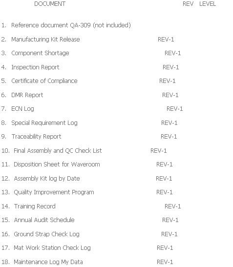
14.0 Documents, Forms and Records
A listing of various documents, forms, and reports used during the manufacturing cycle is given below.