


A PCB Assembly’s Journey Through the Micron Floor
A PCB Assembly’s Journey Through the Micron Floor
A finished assembly does not move directly from a box of components to shipment. It follows a planned route through documentation review, material control, SMT or Through Hole assembly, inspection, test, and final release—with each handoff protecting the design intent.
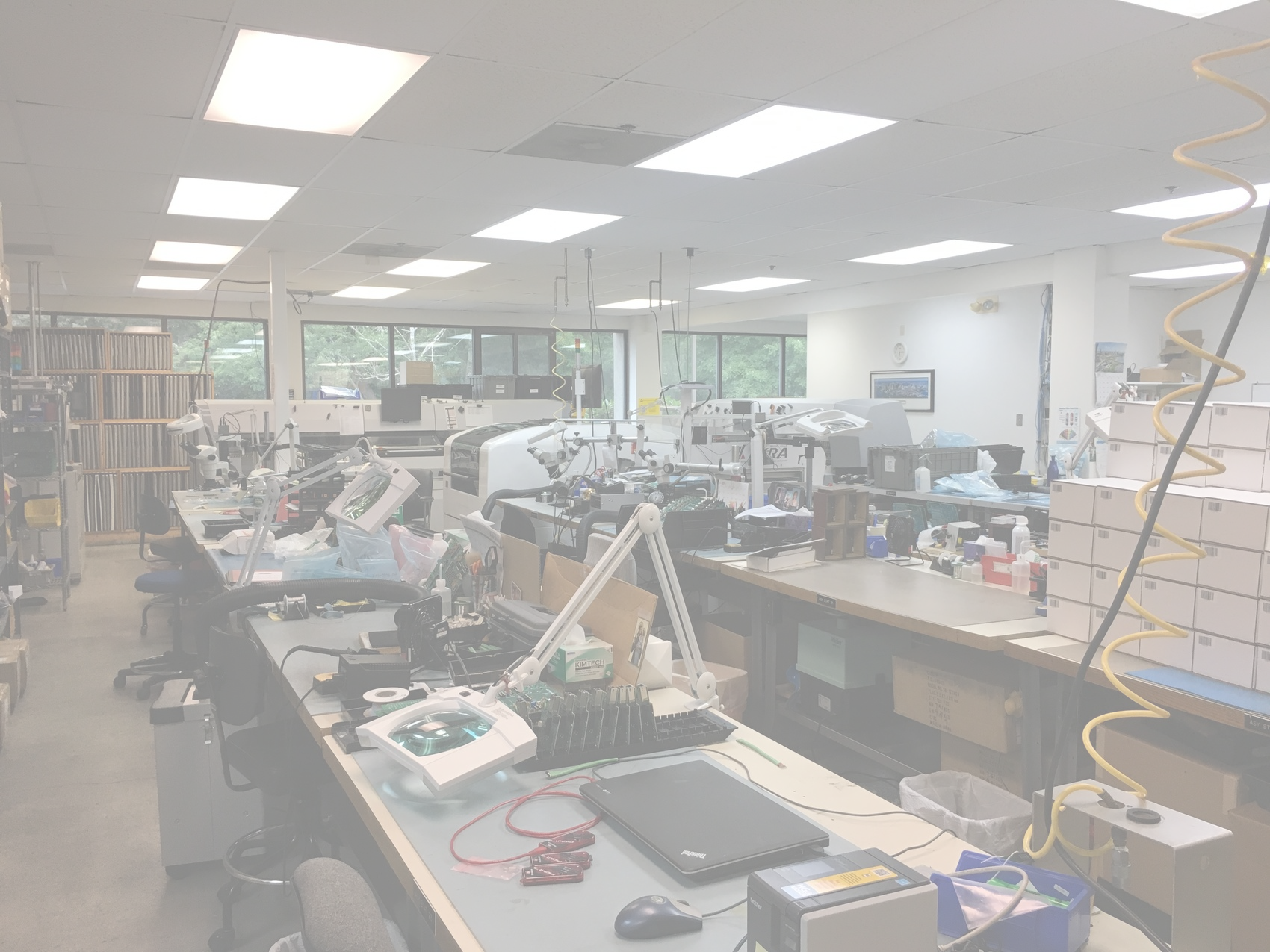
From design data to a documented shipment
The route is controlled, but it is not one-size-fits-all
A prototype, a mixed-technology control board, and a repeat production assembly may pass through many of the same departments, but they do not necessarily need the same process, inspection coverage, test plan, or records. The route should match the product and the customer’s requirements.
Where the board goes
Receiving, preparation, stencil printing, placement, reflow, secondary assembly, inspection, test, cleaning, packaging, and shipment as the build requires.
What travels with it
Revision-controlled files, traveler instructions, inspection criteria, programming details, test results, labels, serial information, and customer-specific records.
Six connected stages, with checks at every handoff
The exact routing can change by program. What should not change is the discipline used to confirm the current revision, control materials, follow the build plan, verify workmanship and function, and close the record before shipment.
Review & launch
Confirm the build package, revision, sourcing model, quantities, schedule, workmanship requirements, test intent, and special instructions.
Materials & kit control
Receive and identify boards, components, stencils, hardware, and customer-supplied material; surface shortages or discrepancies before the build starts.
SMT assembly
Print solder paste, place components, run a controlled reflow profile, and inspect the assembly using the coverage defined for the program.
Through Hole & integration
Add connectors, switches, power parts, hardware, wiring, or enclosure content through hand, wave, mixed-technology, and electromechanical operations.
Inspection, test & programming
Apply AOI, X-ray, visual inspection, electrical test, functional test, firmware loading, or serialization according to the approved scope.
Final release & shipment
Complete final checks, close travelers and records, verify labels and packaging, then release the assembly for protected shipment.
The work moves from automated precision to skilled hands
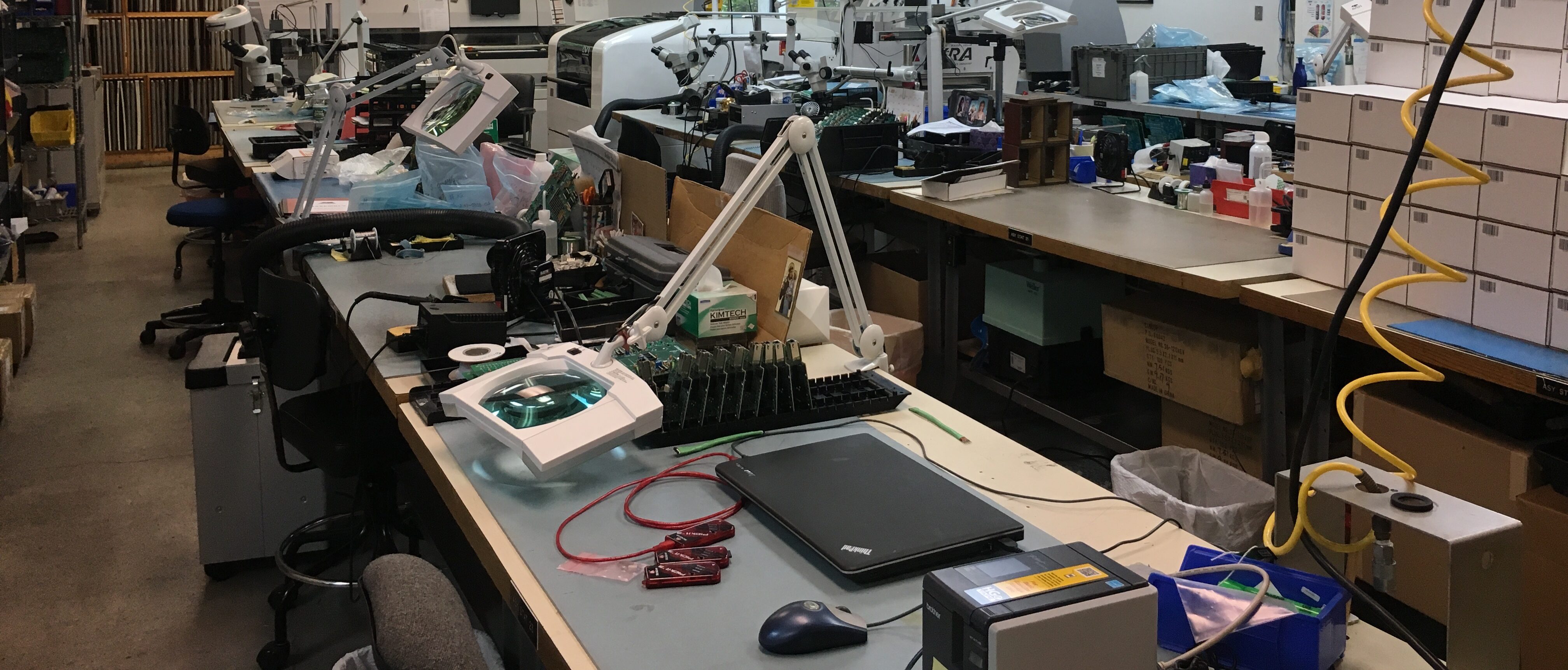
Modern PCB assembly is not purely automated and it is not purely manual. The strongest manufacturing path uses each where it adds value: controlled equipment for repeatable process steps, experienced technicians for mixed technology and secondary operations, and clear inspection and test criteria throughout.
The core equipment connects print, placement, heat, inspection, and Through Hole work
Equipment does not replace process discipline. It makes a defined process repeatable. Programming, setup verification, profiling, inspection criteria, and trained review still determine how effectively each machine supports the build.
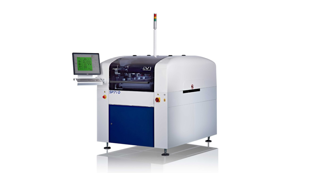
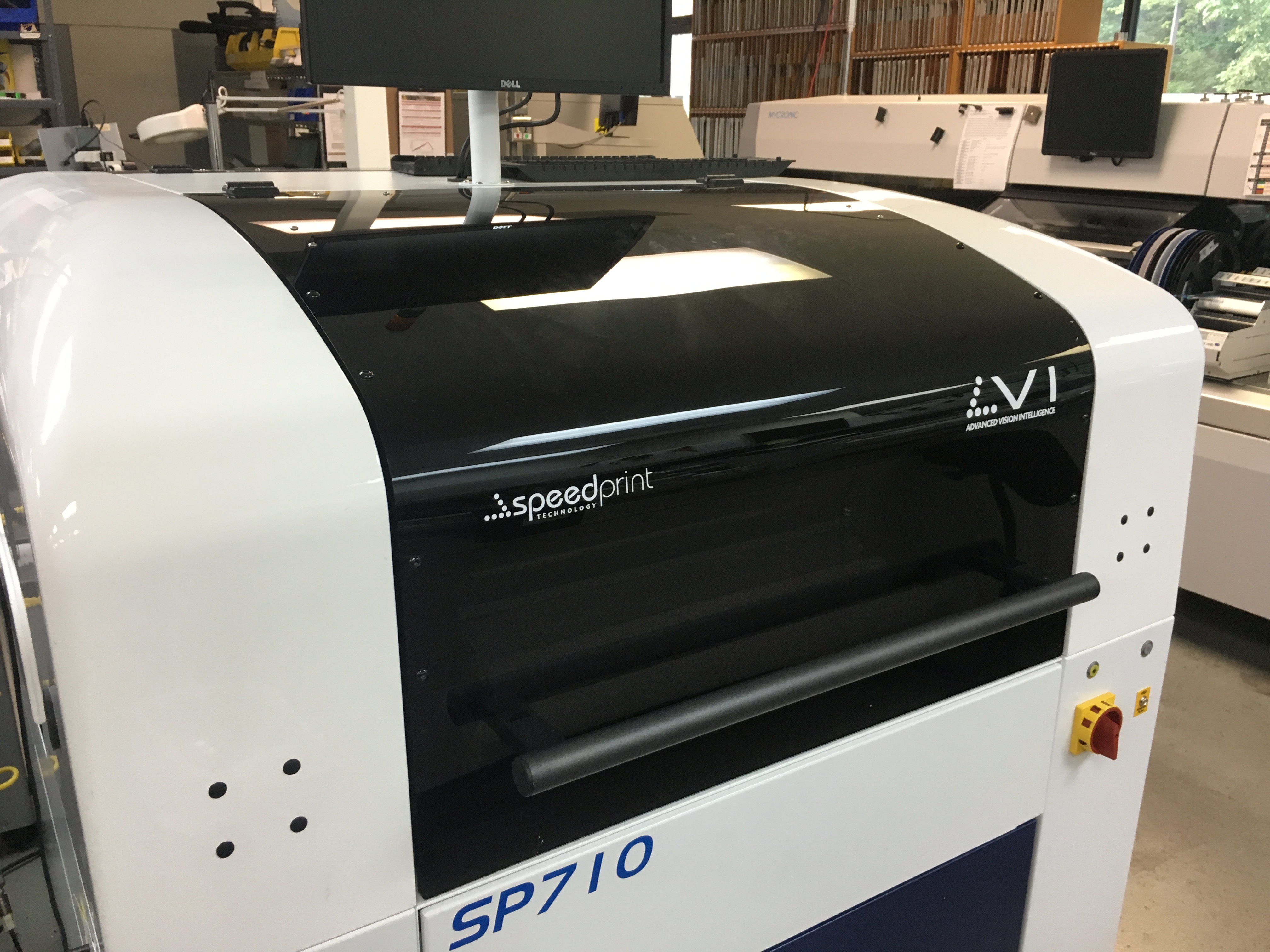
SpeedPrint SP710
Precise stencil-to-board alignment supports consistent solder paste deposition before component placement.
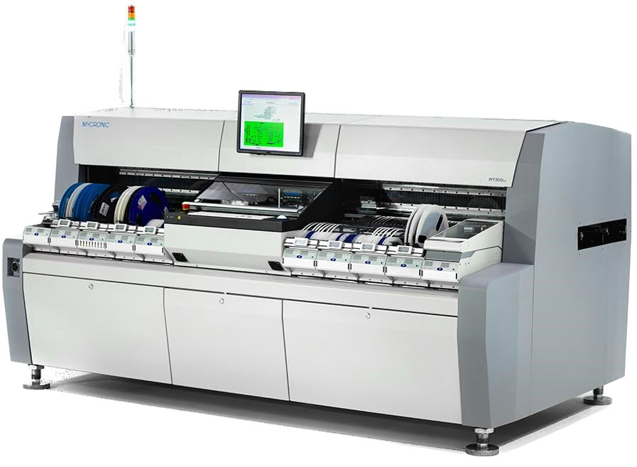
Mycronic MY300 & MY200
Vision-guided placement supports fine-pitch packages, QFN, BGA, and small passive components.
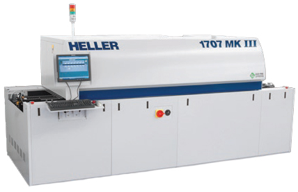
Heller 1707 MKIII
Controlled multi-zone profiles help form repeatable solder joints across assemblies with different thermal demands.
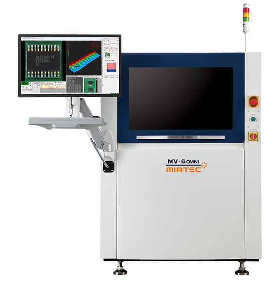
Mirtec MV-6 Omni 3D AOI
Three-dimensional optical inspection helps evaluate placement, polarity, component presence, and visible solder conditions.
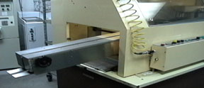
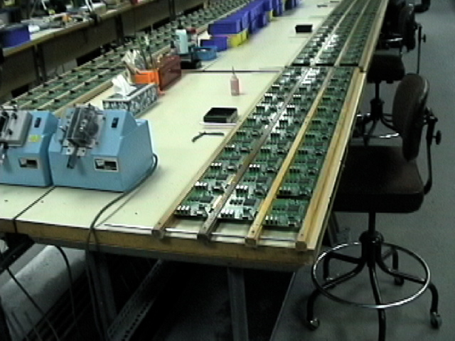
Controlled wave soldering and skilled hand assembly
Through Hole work may use wave soldering, selective hand soldering, fixtures, and technician-controlled operations based on the board geometry, component mix, volume, and workmanship requirements.
What happens as the assembly moves through the floor
The stages below describe the connected manufacturing logic. Individual projects may add first-article holds, special processes, customer approvals, coating, calibration, burn-in, or other program-specific gates.
Project review and launch planning
The build begins with a review of what is being made and how success will be measured. The team aligns the BOM, Gerbers or ODB++, pick-and-place data, assembly drawings, revision level, quantities, schedule, sourcing model, solder requirements, inspection scope, programming, test, labels, and records.
- Resolve mismatched revisions and unclear assembly notes before production
- Identify DFM, material, stencil, panel, test-access, or special-process questions
- Prepare the traveler, route, and customer-specific instructions
Receiving, material verification, and kit readiness
Turnkey, consigned, and hybrid builds all depend on knowing what has arrived, what matches the BOM, and what is still missing. Components, bare boards, stencils, hardware, and customer-supplied materials are identified and routed for the build.
- Confirm line items, quantities, part identity, board revision, and kit status
- Surface shortages, damaged material, substitutions, and open approvals
- Apply appropriate ESD and moisture-sensitive handling controls
SMT programming, printing, placement, and reflow
For surface-mount work, the production path connects stencil printing, feeder and placement setup, component verification, and profile-controlled reflow. Each stage depends on accurate data and a setup that matches the released assembly.
- Apply solder paste with controlled alignment and print consistency
- Program and verify component locations, rotations, packages, and polarity
- Use a thermal profile appropriate to the board, paste, and component mix
Through Hole, secondary operations, and electromechanical integration
After SMT—or as the primary route for some assemblies—connectors, switches, relays, transformers, power parts, mechanical hardware, wires, and other odd-form components may be installed. Some projects continue into subassemblies or finished enclosures.
- Coordinate manual insertion, hand solder, wave solder, lead trim, and hardware
- Verify orientation, mechanical fit, solder quality, and mixed-technology sequencing
- Add wiring, harnesses, labels, torque-controlled hardware, and enclosure content as specified
Related capabilities: Through Hole assembly and electromechanical assembly and box build.
Inspection, electrical test, programming, and feedback
Inspection confirms workmanship; test confirms electrical or product behavior. The appropriate combination depends on component types, access, risk, volume, and what the customer needs the assembly to prove before shipment.
- Use AOI and visual inspection for visible placement and workmanship conditions
- Use X-ray where hidden solder joints or internal conditions require review
- Apply ICT, flying-probe, functional test, programming, serialization, and result capture as scoped
Final inspection, documentation closeout, packaging, and shipment
Release is the final manufacturing gate, not an administrative afterthought. The assembly, records, labels, test status, and packaging should all agree with the program requirements before the order leaves the floor.
- Confirm final workmanship, cleaning, labels, serialization, and configuration
- Close travelers, inspection records, test results, programming logs, and required reports
- Use protective ESD-safe packaging and customer-specific pack-out as required
The same floor supports different manufacturing strategies
The physical equipment may be familiar from one job to the next, but the decisions around setup, hold points, inspection, test, documentation, and release can be very different.
Learn quickly and capture findings
First articles may include additional review, DFM feedback, engineering questions, controlled rework, ECO intake, test development, and documentation intended to support the next build.
Repeat an approved process reliably
Stable builds depend on released revisions, repeatable setup data, approved materials, defined acceptance criteria, established test coverage, and a clear response when something changes.
Coordinate SMT, Through Hole, and mechanics
The route must account for component height, thermal mass, solder sequence, washing, fixtures, hand access, inspection access, hardware, wiring, and final integration.
Plan the evidence before the build
Customer-defined IPC class, traceability, archived profiles, inspection records, test data, serialization, labeling, and retention requirements should be aligned during launch.
What customers can provide before the build reaches the floor
A complete package helps, but it does not need to be perfect to start the conversation. The most important step is to distinguish released requirements from assumptions and details that are still changing.
- BOM with manufacturer part numbers, alternates, quantities, DNP notes, and revision
- Gerbers or ODB++, fabrication notes, panel details, and board revision
- Pick-and-place or centroid data with correct rotations and board side
- Assembly drawings, polarity notes, mechanical drawings, and special instructions
- Target quantities, schedule goals, and prototype, pilot, or production context
- Turnkey, consigned, or hybrid material preference and any customer-supplied parts
- IPC class, solder type, cleaning, coating, labeling, serialization, and packaging needs
- Test intent, firmware, fixtures, pass/fail criteria, reports, and traceability requirements
Related Micron capabilities
Use these pages to look more closely at the manufacturing stages described in this journey.
A reliable build starts before the first board reaches the line
Share the design package, quantities, sourcing preferences, test needs, and what is still changing. Micron can help identify the route from quote review to a controlled, inspectable, and repeatable assembly.