Robotics Electronics: Designing for Vibration, Serviceability, and Revision Changes
A robotics PCB does more than process signals. It lives inside a moving system, connects to motors and sensors, may need to be serviced in the field, and often changes as the robot matures. Designing for those realities early can make the difference between a promising prototype and a dependable product.
Design the electronics as part of the robot—not as a board that happens to fit inside it
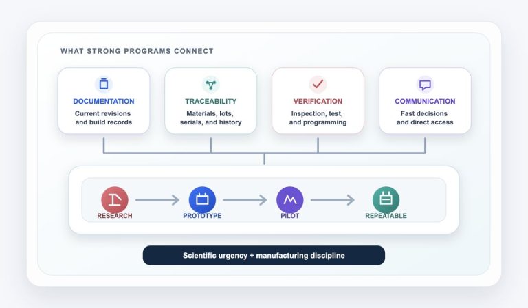
The strongest robotics electronics programs connect mechanical loading, service strategy, and configuration control from the beginning. That changes decisions about board mounting, connectors, harnesses, module boundaries, test access, labeling, firmware, and how future revisions will enter the field.
Design the load path
Vibration should travel through the chassis and mounting system—not repeatedly flex unsupported boards, heavy components, solder joints, or cable terminations.
Plan how it will be serviced
A technician should be able to identify the correct module, disconnect it safely, replace it, restore configuration, and verify operation without creating a second problem.
Control the full configuration
The working revision is not just a PCB number. It is the approved combination of board, BOM, firmware, harness, mechanical interface, calibration, and test method.
These priorities reinforce one another
A connector selected for positive retention can also improve service replacement. A modular controller can isolate vibration-sensitive functions and make revisions easier to introduce. Clear serialization can support field service and keep old and new configurations from being mixed.
Robotics electronics face more than one kind of movement
The relevant environment depends on the robot. A fixed industrial arm, mobile platform, warehouse system, laboratory robot, autonomous vehicle, and end-of-arm tool can expose electronics to very different loads. The design team should define the actual use case rather than relying on a generic “rugged” requirement.
Continuous vibration
Motors, gearboxes, pumps, fans, wheels, and moving structures can create repeated loads that accumulate over operating time.
Shock and abrupt motion
Stops, impacts, tool engagement, docking events, transport, and handling can create short-duration loads beyond normal operation.
Repeated cable flex
Harnesses may bend through thousands or millions of cycles, transferring force into connectors unless routing and strain relief are planned.
Electrical noise
Motor drives, switching power, long cables, encoders, and high-current loads can complicate grounding, shielding, filtering, and test.
Thermal cycling
Enclosures, motors, power electronics, ambient changes, and duty cycles can repeatedly expand and contract materials and interfaces.
Ongoing product evolution
Sensors, compute modules, motors, safety interfaces, firmware, and component availability often change as the platform matures.
Design for vibration by controlling where mechanical energy goes
Vibration problems are rarely solved by one “rugged” component. The load path runs from the robot structure into the enclosure, mounts, PCB, components, connectors, and harnesses. Each interface can either control the load or concentrate it.
Robot Structure
Source motion, motor energy, impacts, and resonance.
Enclosure
Mounting surfaces, stiffness, isolation, and fasteners.
PCB Supports
Standoffs, spacing, board thickness, and restraint.
Components
Mass, lead geometry, retention, and solder joints.
Connections
Connectors, cables, strain relief, and mating security.
Support the board where it needs support
Mounting-hole placement, standoff spacing, board dimensions, cutouts, and heavy-component locations affect board deflection. Large unsupported spans deserve special attention.
Retain connectors and high-mass parts
Latching or locking connectors, Through Hole attachment, brackets, staking, approved adhesives, or other specified retention methods may be appropriate depending on the load and service plan.
Keep cable loads out of the solder joints
Use strain relief, controlled bend radii, adequate service loops, harness anchors, and connector orientation that does not turn normal motion into repeated leverage on the PCB.
Validate the real operating profile
Direction, frequency, amplitude, duration, duty cycle, resonance, shock, mounting orientation, and powered operation all affect whether a test meaningfully represents the product.
Use the applicable environmental requirement—not a generic vibration claim
IEC 60068-2-6 describes a standardized method for sinusoidal vibration testing. It is a useful reference point, but the OEM still needs to define the correct severity, mounting, axes, operating state, acceptance criteria, and any shock or random-vibration requirements for the actual robot.
Serviceability starts with a realistic repair path
A robot that works in the lab may eventually operate at a customer site, on a production line, in a warehouse, or inside specialized equipment. When downtime matters, the electronics should help a technician identify the problem and replace the right item without disassembling half the machine.
Identify
Use diagnostics, logs, labels, and visible status information.
Isolate
Determine which module, cable, sensor, or interface has failed.
Replace
Access and exchange the part without disturbing unrelated systems.
Configure
Restore firmware, parameters, identity, or calibration as required.
Verify
Run a defined check before returning the robot to service.
Use clear module boundaries
Separate power, control, I/O, sensor interfaces, communications, and replaceable wear items when the architecture and service strategy justify it.
Make interfaces difficult to misconnect
Keying, polarization, labels, connector differentiation, pin protection, and logical cable routing reduce mistakes during hurried service.
Plan access before enclosure release
Check tool clearance, fastener access, cable reach, connector release tabs, board extraction, heatsink removal, and whether service requires moving unrelated assemblies.
Design the verification step
Test points, built-in diagnostics, status indicators, programming access, serial identification, and a concise service test can reduce uncertainty after replacement.
Protection and serviceability can pull in opposite directions
Potting, aggressive staking, sealed connectors, permanent adhesives, and deeply buried electronics may improve resistance to some environments but make repair difficult or impossible. The right choice depends on whether the product is replaced as a sealed module, repaired at a depot, or serviced at component or board level.
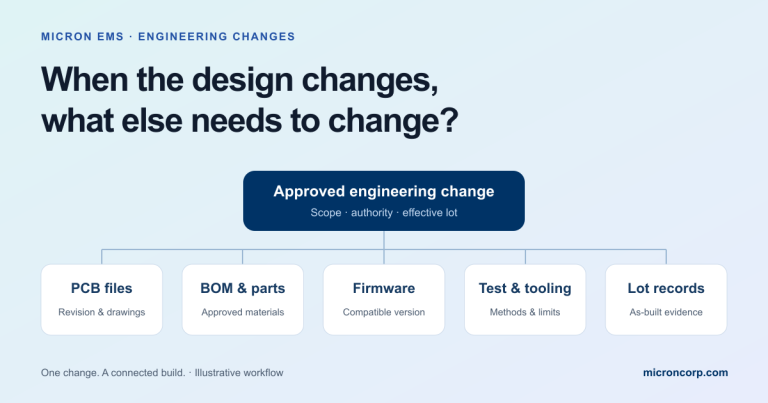
Revision control must follow the working system—not just the PCB
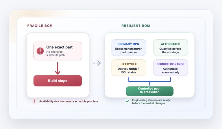
Robotics platforms evolve. A sensor may change, a motor interface may be updated, a component may become unavailable, firmware may add a function, or a harness may be rerouted. The important question is not only “what changed?” but “which combinations are approved to work together?”
PCB revision, BOM revision, approved alternates, component substitutions, assembly notes, and workmanship requirements.
Harness revision, connector pinout, sensor type, motor interface, power architecture, mechanical mounting, and enclosure clearances.
Firmware image, bootloader, programmable settings, serial-number rules, calibration data, security material, and factory defaults.
Test fixture revision, test software, limits, expected outputs, inspection criteria, functional sequence, and acceptance records.
Serial or lot range, production date, installed options, backward compatibility, retrofit instructions, spares strategy, and service documentation.
A replacement board may fit mechanically and still be the wrong replacement
Connector compatibility does not prove firmware compatibility, sensor support, motor behavior, calibration, safety-interface behavior, or test coverage. Revision effectivity and a controlled configuration record help prevent a physically compatible but functionally incorrect assembly from entering the field.
Good robotics design balances priorities instead of optimizing each one in isolation
Many decisions improve one objective while complicating another. Make those tradeoffs explicit during design review so manufacturing and service do not discover them after release.
Secure the component without making service destructive
Staking or adhesive may help with vibration, but the selected material, location, cure, and removal method should match whether the component is expected to be replaced.
Protect the electronics at the right assembly level
A sealed replaceable module may be more maintainable than a serviceable board buried inside a difficult enclosure. Define the intended service level before selecting protection methods.
Do not use every millimeter of enclosure space
Connector release, harness bends, airflow, board support, test access, fastener tools, tolerance stack-up, and future component changes all need physical margin.
Decide what must remain stable across revisions
Mechanical envelope, connector pinout, protocol, supply rails, mounting, software interface, and service procedure may need formal compatibility rules before a revision is approved.
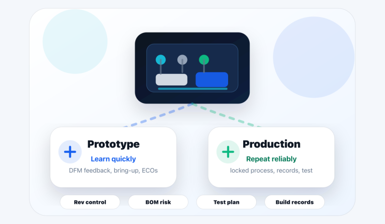
Use early builds to create a production-ready robotics assembly
A prototype can prove motion and control, but production readiness requires repeatable assembly, controlled documentation, test coverage, and a plan for changes. This is where a disciplined prototype and NPI process becomes valuable.
Define the operating environment
Document motion, vibration, shock, temperature, contamination, duty cycle, enclosure, mounting, cable movement, and expected service life.
Freeze critical interfaces
Identify the mechanical, electrical, communications, power, firmware, and service interfaces that future revisions must preserve or formally change.
Review DFM and DFT
Evaluate component retention, board support, solder process, connector access, test points, programming, inspection, rework, and fixture needs.
Build and inspect first articles
Use first articles to verify placement, polarity, mechanical fit, harness routing, solder quality, firmware loading, and assembly instructions.
Validate the service workflow
Perform a realistic module replacement, configuration restore, calibration, and return-to-service check before the design is difficult to change.
Lock the configuration record
Connect board, BOM, firmware, harness, mechanical, inspection, test, labeling, serialization, and approved changes for repeat production.
Manufacturing should connect the board to the complete robotic system
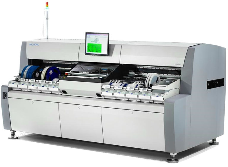
Robotics programs commonly combine fine-pitch SMT, rugged connectors, Through Hole components, power devices, harnesses, enclosures, firmware, calibration, and functional test. The EMS plan should account for those interactions rather than treating each operation as an unrelated purchase.
Mixed-technology assembly
SMT and Through Hole processes can be coordinated around fine-pitch control electronics, retained connectors, power components, and mechanical interfaces.
Electromechanical integration
Box build and electromechanical assembly can connect boards, harnesses, switches, fans, displays, brackets, labels, and enclosures into a controlled assembly path.
Programming and verification
Testing and programming can include firmware loading, serialization, interface checks, fixture coordination, functional test, and production records as scoped.
Revision and build records
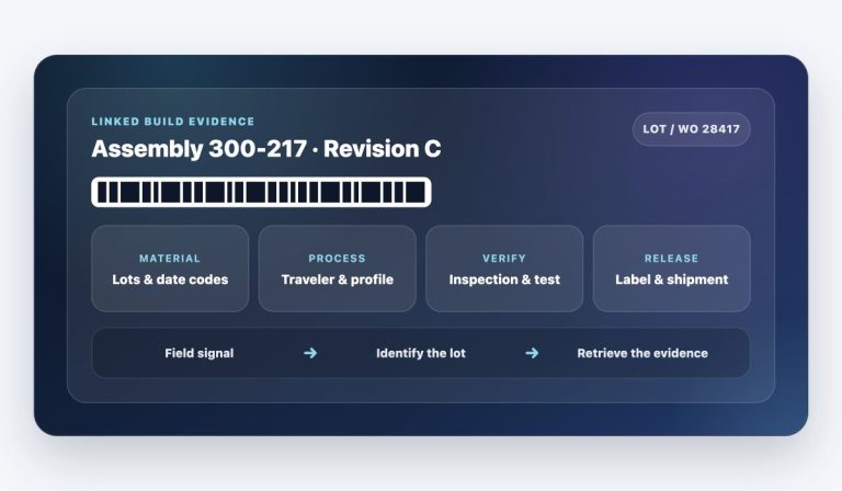
Travelers, ECO notes, labels, inspection criteria, test revisions, firmware identifiers, and lot or serial records help carry approved decisions into repeat builds.
Massachusetts robotics teams benefit from short engineering-to-manufacturing feedback loops
Massachusetts has a deep robotics ecosystem spanning startups, established OEMs, research teams, integrators, suppliers, and specialized talent. MassRobotics supports companies as they develop, prototype, test, commercialize, and scale robotics and connected-device technologies.
For a robotics team, a local EMS relationship can make practical work easier: reviewing a changing data package, walking through a mechanical interface, discussing test intent, resolving a harness question, evaluating a first article, or coordinating a revision without adding distance to every decision. Micron supports robotics and automation programs from its Norwood, Massachusetts manufacturing facility as part of its broader industry-focused EMS capabilities.
What to send your EMS partner for a robotics electronics build
A complete package helps the manufacturing team understand not only the PCB, but also how the assembly is mounted, connected, programmed, tested, serviced, and revised. Send what is available; open questions can be identified during review.
Core electronics data
- BOM with exact manufacturer part numbers and approved alternates
- Gerbers, ODB++, fabrication notes, stackup, and board revision
- Pick-and-place data, assembly drawings, polarity, and DNP notes
- Solder process, coating, staking, adhesive, cleaning, and workmanship requirements
Mechanical and environmental context
- Enclosure, standoff, bracket, heatsink, and board-mounting drawings
- Connector retention, harness drawings, strain relief, and cable-motion details
- Vibration, shock, thermal, contamination, ingress, and duty-cycle requirements
- Known high-mass components, unsupported spans, and field-failure concerns
Programming, test, and configuration
- Firmware images, versions, loading instructions, keys, and configuration rules
- Test procedure, fixture information, communications interfaces, and pass/fail limits
- Calibration requirements, serial-number format, labels, and traceability needs
- Expected relationship between board, firmware, harness, test, and robot revision
Program and service intent
- Prototype, pilot, and production quantities with timing goals
- Turnkey, consigned, or hybrid sourcing preference
- Field-replaceable module strategy and expected service procedure
- Compatibility, spares, retrofit, ECO, and future revision expectations
Robotics electronics manufacturing questions
Should every robotics PCB use Through Hole connectors?
No. Connector technology should follow current, signal integrity, board space, mating cycles, retention, cable loading, vibration, assembly process, and service requirements. Some applications benefit from Through Hole or additional mechanical retention; others are well served by properly selected surface-mount connectors and enclosure-level support.
Does conformal coating solve vibration problems?
Not by itself. Conformal coating is primarily an environmental protection process. Depending on the material and application, it may add some support, but it does not replace appropriate board mounting, component retention, connector selection, strain relief, solder-joint design, or vibration validation.
When should serviceability be reviewed?
Before the enclosure and harness architecture are finalized. A simple service exercise during prototype or NPI—remove the module, install a replacement, restore configuration, and verify operation—often reveals access, labeling, cable, fastener, firmware, and test issues while they are still inexpensive to correct.
How should hardware and firmware revisions be linked?
Use a controlled configuration record that identifies approved board, BOM, firmware, bootloader, programmable settings, test procedure, harness, and mechanical compatibility. Labels, serial records, travelers, programming logs, and effectivity rules can help preserve that link through manufacturing and field service.
Can Micron support prototype robotics builds that are still changing?
Yes. Micron’s prototype and NPI work is structured around evolving designs, BOM review, DFM/DFT feedback, first articles, inspection, programming, functional-test planning, ECO intake, and the documentation needed to move toward a repeatable build.
Connect the robotic controller to the full manufacturing path
Building electronics for a robot or automation platform?
Send Micron your BOM, board data, mechanical context, harness information, programming and test intent, quantities, and schedule goals. If the design is still evolving, send what you have and identify the questions that need manufacturing input.